
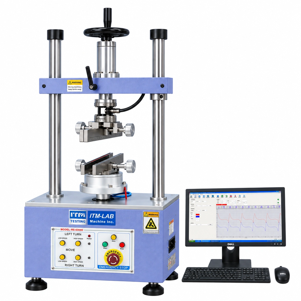
Mechanical failures in electronic products often begin at relatively small interfaces: a connector that becomes difficult to insert, a hinge that loses its holding resistance, or a cable connection that separates under load.
Consider a laptop under development. Its USB-C connector must provide acceptable insertion and extraction performance, the hinge must maintain controlled rotational resistance, and internal cable connections must withstand specified mechanical loads.
These requirements belong to the same product, but they involve different loading directions, measurement systems and fixtures.
For electronics manufacturers, selecting mechanical testing equipment begins with the individual component and its intended operation—not simply the finished product category.
Where Mechanical Failures Occur in Electronic Products
Electronic assemblies contain several mechanical interfaces that experience different types of loading during manufacturing, assembly and normal use.
Some must withstand a defined force without separating. Others are expected to operate repeatedly while maintaining acceptable mechanical performance.
A connector needs sufficient contact retention without excessive mating resistance. A laptop hinge must provide controlled resistance throughout its operating angle. A button needs consistent actuation, while a cable termination must remain mechanically secure.
Structural components introduce additional requirements. PCB assemblies may be exposed to bending during handling or assembly, while selected display modules and bonded components may require mechanical strength evaluation.
These applications cannot be assessed using a single generic force test.
[IMAGE 1 — INSERT HERE | FULL WIDTH]
Mechanical Test Points in Electronic Products
Suggested Alt Text: Mechanical testing points in electronic products including connectors, hinges, buttons, cable assemblies, PCB and structural components
Which Mechanical Test Does Your Product Need?
The appropriate test depends on the mechanical event being reproduced and the information required to evaluate the result.
The following matrix provides an initial reference for common electronic product applications.
| Component / Application | Mechanical Test | Primary Measurement | Main Testing Concern |
|---|---|---|---|
| USB / industrial connector | Insertion and extraction | Force–Travel | Mating resistance and alignment |
| Connector interface | Repeated mating durability | Cycles / specified performance checks | Wear and operating consistency |
| Button / switch | Actuation force | Force–Displacement | Operating force and contact position |
| Laptop / device hinge | Opening and closing torque | Torque–Angle | Rotational resistance |
| Cable / terminal connection | Pull or retention test | Pull Force / Failure Location | Joint integrity |
| PCB / structural component | Bending or compression | Force / Deflection | Mechanical deformation or failure |
| Bonded electronic assembly | Pull, peel or shear, as applicable | Force / Failure Mode | Attachment integrity |
These measurements describe different mechanical behaviors. A connector force tester, hinge torque tester and universal testing machine may all measure mechanical loads, but their motion control and specimen arrangements are not interchangeable.
Connector and Cable Testing
Connector insertion and extraction testing evaluates resistance during mating and unmating. Where required, a force–travel curve can reveal how the load changes throughout the movement rather than reporting only a maximum value.
Cable and terminal pull testing addresses a different requirement: whether a connection can withstand a specified tensile load.
The measured force must be considered alongside the failure location. A connection that separates at the intended joint is not equivalent to a specimen that slips inside the grip.
ITM-LAB's RS-6600A provides a starting point for compatible connector insertion and extraction applications. For selected component pull tests, a suitably configured RS-8010A may be considered.
Detailed connector procedures are covered in ITM-LAB's existing connector force testing guides.
Repeated Mechanical Operation
A component's initial performance does not necessarily describe its behavior after repeated use.
Connector mating durability, button life and hinge endurance testing reproduce defined operating sequences over a specified number of cycles.
These applications require suitable motion control, specimen positioning and the specified operating stroke or angle. Depending on the procedure, additional measurements may be required before, during or after cycling.
Structural and Bonded Components
PCB assemblies, display-related components and bonded electronic structures may require tensile, compression, bending, peel or other application-specific tests.
The loading arrangement depends on specimen geometry and the applicable procedure.
A configurable universal testing machine may accommodate several compatible static mechanical tests, but the required fixtures and measurement accessories must be reviewed individually.
For example, a PCB bending arrangement requires suitable support spacing and loading geometry. It should not be treated as an ordinary tensile test simply because both procedures use force measurement.
[IMAGE 2 — INSERT HERE | FULL WIDTH]
Electronic Mechanical Testing Methods and Measurement Requirements
Suggested Alt Text: Electronic mechanical testing applications showing connector force, hinge torque, button testing, cable pull and component bending
Why Fixtures and Alignment Affect Test Results
The fixture is part of the measurement system, not merely a device for holding the specimen.
This becomes especially important when testing electronic components with small dimensions, irregular shapes or delicate connection points.
A machine may provide sufficient capacity and measurement performance, yet produce misleading results if the loading direction or specimen positioning is incorrect.
A Connector Alignment Example
During connector insertion testing, the mating components should move along the intended insertion axis.
Even when the test speed and force range are correctly specified, an off-axis mating arrangement can introduce additional resistance into the recorded force–travel curve.
Before comparing results, engineers should verify the connector position, mating direction and fixture repeatability.
Increasing the machine's capacity will not solve an alignment problem.
Similar issues arise in other electronic applications.
| Test Application | Fixture Problem | Possible Effect |
|---|---|---|
| Connector insertion | Mating axis misalignment | Additional side loading and resistance |
| Button actuation | Incorrect probe position or contact geometry | Unrepresentative operating force |
| Hinge torque | Test rotation axis differs from hinge axis | Additional measured resistance |
| Cable pull | Specimen slips or is damaged by the grip | Invalid force result or failure location |
| PCB bending | Incorrect support spacing or loading position | Unrepresentative deformation behavior |
For repeated testing, specimen positioning also needs to remain consistent between operators and test cycles.
If the same component is installed differently each time, some of the observed variation may come from the fixture rather than the product.
This is particularly relevant to production QC, where repeatable setup is essential for comparing results across batches.
Custom fixtures may be necessary when conventional grips cannot reproduce the intended loading direction or securely accommodate the specimen geometry.
[IMAGE 3 — INSERT HERE | FULL WIDTH]
Fixture Alignment and Its Effect on Electronic Mechanical Testing
Suggested Alt Text: Correct and incorrect fixture alignment in electronic connector, button, hinge and cable testing
Selecting the Measurement and Control System
Once the test method and fixture arrangement are established, the next step is determining what the equipment must measure and control.
Force capacity is only one part of that decision.
Electronic mechanical testing may involve linear movement, rotational movement or repeated operation. The appropriate system depends on the required motion and the data specified by the test procedure.
| Testing Requirement | Equipment Configuration to Check |
|---|---|
| Single pull or push | Force range, travel, loading direction and fixture |
| Connector insertion / extraction | Axial alignment, speed, stroke and force–travel measurement |
| Repeated operation | Cycle count, motion control, operating rate and stopping conditions |
| Hinge rotation | Torque range, angle and rotational axis |
| Component strength | Load cell, fixture, travel and deformation measurement |
Peak Force, Curves and Repeated-Cycle Data
A peak force value answers a specific question: what was the maximum recorded force during the defined test?
It does not necessarily describe the component's behavior throughout its movement.
For a connector, force–travel data may be needed to evaluate the mating process. For a hinge, torque–angle data can provide information about resistance over the operating range.
Repeated-cycle testing addresses another question: whether the component maintains the required performance after a specified number of operations.
A machine designed to record a single peak force is not automatically suitable for evaluating mechanical performance over repeated cycles.
The required measurement and monitoring functions should be established before selecting the controller and software configuration.
[IMAGE 4 — INSERT HERE | FULL WIDTH]
Different Tests Require Different Measurement Data
Suggested Alt Text: Comparison of force travel, torque angle and repeated cycle data used in electronic mechanical testing
Electronic Mechanical Testing Equipment Selection
A useful equipment shortlist begins with the required mechanical action.
An axial connector insertion test, a rotating hinge test and a static component pull test should not be grouped together simply because each involves measuring a mechanical load.
ITM-LAB offers different testing equipment series for these applications.
| Testing Application | ITM-LAB Equipment Direction | Key Configuration Consideration |
|---|---|---|
| Connector insertion / extraction | RS-6600A | Connector geometry, axial travel and force range |
| Connector mating durability | RS-8115A | Stroke, operating rate and cycle requirements |
| Button actuation / life | Application-specific button testing system | Pressing position, force, stroke and cycles |
| Hinge torque / endurance | RS-6300F / RS-6300T-H | Torque range, angle and fixture alignment |
| Cable / component pull | RS-8010A with suitable configuration | Expected force, gripping and failure location |
| Component tensile / compression / bending | RS-8010A / RS-8000 | Load range, specimen dimensions and fixtures |
These are initial equipment directions, not fixed configurations for every product. A final recommendation requires the actual device under test, relevant procedure and expected measurement conditions.
Can One UTM Perform Every Mechanical Test on an Electronic Product?
Not necessarily.
A configurable UTM may support several compatible static force tests, including tensile, compression and bending, when equipped with suitable fixtures and measurement systems.
Connector mating durability, button life and hinge torque testing involve different motion and control requirements. These applications may require dedicated equipment.
A laboratory should group its testing needs by mechanical action and measurement method rather than attempt to replace every system with one machine.
Three Practical Laboratory Configurations
The appropriate equipment combination depends on the manufacturer's product range and testing workload.
The following examples illustrate how different electronics laboratories might organize their mechanical testing requirements.
Configuration A — Connector & Cable Quality Control
For connector and cable assembly manufacturers, mechanical testing is often part of routine production quality control.
Insertion force, extraction force and selected pull-strength requirements may need to be evaluated across different component types.
An initial configuration could include the RS-6600A for compatible connector force testing and an appropriately configured RS-8010A for selected pull-testing applications.
Although both systems measure force, the connector's mating geometry and the cable assembly's gripping requirements must be considered separately.
Where repeated connector operation is also required, a dedicated durability configuration such as the RS-8115A may be relevant.
Configuration B — Consumer Electronics Durability
A smartphone, earphone, tablet or laptop may contain several interfaces that undergo repeated mechanical operation throughout the product's service life.
A laboratory evaluating these products may need connector mating durability, button life and hinge torque or endurance testing.
The challenge is not simply reaching a target cycle count. Each test must reproduce the specified movement while maintaining suitable specimen positioning and control.
ITM-LAB's RS-8115A and relevant button and hinge testing systems provide starting points for reviewing these applications.
The required stroke, angle, operating rate, cycle count and any specified performance checks should be established before selecting the equipment.
Configuration C — Electronic Component R&D
Development laboratories often work with different materials, structural parts and mechanical connections rather than one fixed specimen type.
A configurable UTM can provide a practical testing platform for several compatible tensile, compression and bending procedures.
ITM-LAB's RS-8010A and RS-8000 series offer different force capacity options, while application-specific fixtures can support different loading arrangements.
The expected working force, specimen dimensions, travel, measurement range and applicable procedure should guide the final selection.
A larger maximum machine capacity does not automatically provide better measurement performance for smaller electronic components.
These laboratory configurations are examples rather than fixed equipment packages. Some facilities may need only one testing system, while others require several specialized machines.
[IMAGE 5 — INSERT HERE | FULL WIDTH]
Electronic Mechanical Testing Laboratory Configuration
Suggested Alt Text: ITM-LAB testing equipment configurations for connector quality control, consumer electronics durability and component R&D
What Engineers Should Specify Before Requesting a Quotation
Providing clear application information allows the equipment manufacturer to review the required machine configuration and identify potential fixture or measurement issues before quotation.
For electronic mechanical testing projects, the following details are particularly useful:
-
Device under test: Component name, photographs, dimensions and relevant assembly details.
-
Mechanical action: Pulling, pushing, insertion, extraction, rotation or repeated operation.
-
Expected measurement range: Force or torque range, where known.
-
Test conditions: Speed, travel, angle, operating rate and cycle count.
-
Test method: Applicable standard edition or customer-specific procedure.
-
Additional requirements: Custom fixtures, curve recording, electrical monitoring or other specified functions.
Where the expected force or torque is not yet known, the specimen information and intended test procedure can still provide a starting point for an engineering review.
A clear test specification helps avoid purchasing equipment that has sufficient nominal capacity but lacks the required motion, fixture or measurement configuration.
Conclusion
An effective electronics mechanical testing laboratory starts with the product's actual mechanical requirements, not a generic equipment list.
Connector mating, button pressing, hinge rotation, cable pulling and component strength testing may all involve mechanical loads, but they require different test arrangements and measurement data.
The appropriate system is one that reproduces the intended mechanical action, holds the specimen correctly and provides reliable results over the required measurement range.
Configure a Mechanical Testing System for Your Electronic Product
Testing a connector, button, hinge, cable assembly or structural component?
ITM-LAB provides mechanical testing equipment and application-specific configuration support for electronics R&D and quality control.
Share your DUT details, test method and measurement requirements with our team to review suitable machine configurations and fixtures.
